Mobile robotic platforms (3 vs. 4 wheels vs. tracks)
The mobile platform is the key to your robot’s maneuverability, so it is important to understand the options available when designing it.
Nomenclature:
This section introduces the different components within a mobile platform subassembly. The example mobile platform assembly shows how a frame assembly, caster wheel, and two drive wheel subassemblies attach with fasteners. Before moving forward with the design process, it is important to understand the nomenclature and purpose of the following components:
1. Frame
Assembly – the example consists of 80/20 extrusion and connection brackets for quick
assembly/disassembly, and it supports all other subassemblies.
2. Motor
Mount – serves to attach the motor of choice to the frame assembly. Each motor mount has two sets of clearance
holes: one set to mate with the motor and another to mate with the 80/20. In the Denso
Motor Mount, there are three holes that mate with the motor in a circular
bolt pattern, while there are two holes that attach the motor mount to the
80/20. Notice the larger clearance hole
that allows the motor’s drive shaft to pass through to the wheel hub.
3. Wheel
Hub – serves to attach a wheel (or any other rotating object) to a motor’s drive
shaft. In this example, the wheel hub
mechanically engages the flat portion of the drive shaft through the use of two
set screws. Notice the motor mount must
be attached to the motor prior to attaching the wheel hub. The wheel hub contains a circular pattern of
three threaded holes that mate with the clearance holes on the drive wheel. Fasteners are used to attach the wheel to the
wheel hub, and wheels can be replaced as long as they maintain the same bolt pattern.
4. Drive
Wheel – uses a polar bolt pattern to attach to the wheel hub.
5. Caster
Wheel – has its own mounting axle, is typically free to pivot about a second
(near) vertical axis, and allows for easy rotation of a mobile platform.
3 vs. 4 wheel mobile platforms:
Mobile platforms with less than three wheels typically require a complex system of sensors and control logic to provide balance and are therefore not suitable for the project in this course. Figure 1 shows examples of two wheel platforms.
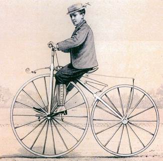
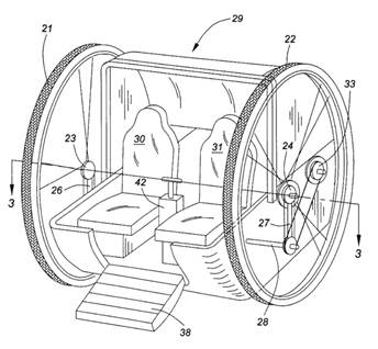
Figure 1: Bicycles and dicycles have fundamental balancing challenges for this project.
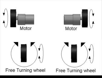
Three wheel platforms are the fewest number of wheels that are innately stable. Since three points form a geometric plane, three wheels also ensures all wheels remain in contact with the ground at all times, thus providing the best available traction for a mobile platform that lacks a suspension system. Figure 2 below illustrates a three wheel layout for a mobile platform; two wheels are powered and the third is a caster wheel which is free to rotate about an axis normal to the page.
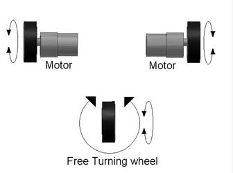
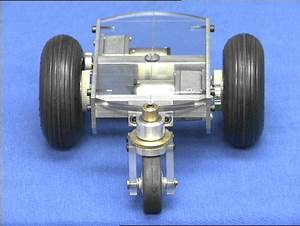
Figure 2: Three wheel mobile platform layout
The next obvious choice would be a four-wheel mobile platform, as shown in figure 3 below. The simplest configuration is two drive wheels (differentially steered) and two caster wheels. From a maneuverability standpoint, this layout is similar in performance to the three wheeled configuration shown above. However, since only three points are guaranteed to form a plane, if the robot is not assembled perfectly OR the surface on which it is driving is not perfectly flat, one wheel is guaranteed to come out of contact with the floor. If this wheel happens to be a drive wheel (which it will), the driver will lose traction and thus controllability of the robot. Automobiles do not suffer from this problem because of their suspension systems.
In general, four-wheel platforms offer superior high speed stability compared to three-wheel platforms. However, typical robot velocities for the DML course projects fall in the lower speed category.
%20R.JPG)
Figure 3: Four wheel mobile platform layout
Tracks:
The final subject discussed under mobile platforms is continuous tracks. Tracks are large treads used on crawler-type vehicles such as tanks, construction equipment and other types of off-road vehicles. Tracks provide superior traction in all types of terrain with the exception of very hard surfaces, such as concrete. They are constructed of either metal or rubber and form a continuous flexible belt that is powered by drive wheels or sprockets. The tracks help distribute the vehicle’s weight more evenly over a larger surface area than wheels through the use of several idler wheels located at the base of the track. A tank with tracks is shown below in Figure 4. Tracked vehicles always employ differential steering.
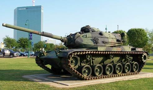
Figure 4: Example of tracked tank with differential drive.