Robot controllers
The controllers used in the course consist of two principal parts: the joysticks/transmitter (figure 1) and the control box/receiver (figure 2). The joysticks and transmitter convert the user’s input into wireless RF signals that are transmitted to the receiver mounted inside the control box via wireless modem. A 12VDC battery is mounted inside the control box and serves as the power source for the robot.
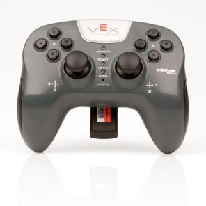
Figure 1: Joysticks / Transmitter
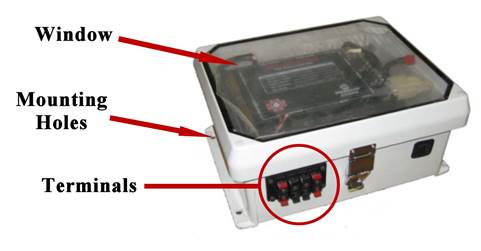
Figure 2: Control Box / Receiver
The control box measures approximately 11.5” wide x 9.5” deep x 5.5” tall (a more detailed CAD model of the control box can be found on the course website). The control box must attach securely to the robot using at least one of the mounting holes in each of the two base flanges of the plastic enclosure, and it must attach in a manner that does not place bending stress on the mounting flanges. No other part of the control box can be used for attachment purposes or to support other parts of your robot design. The control box may mount to the robot in any orientation; however, once mounted to the robot the window on the control box (see figure 2) must be visible (i.e. not upside down) to allow for troubleshooting. The electronics used for the controllers are expensive, so please treat them like a laptop: carry them with two hands, don’t use them around liquids and be careful not to scratch the boxes when working with them.
The controllers provide three relay channels and two proportional channels of control (for a maximum of 5 motors/actuators which can be controlled simultaneously). Relay control is like a typical light switch: either “on” or “off”. Each relay channel either sends +12VDC source voltage to the motor, 0VDC (i.e. nothing) or -12VDC (i.e. reverses polarity); this means the motor connected to the relay channel will either turn CW, sit still, or spin CCW at the rated speed. Proportional control has the ability to send a voltage to the motor proportional to the displacement of the joystick yoke (forward and backward movement). Each proportional channel can therefore send anywhere from -12VDC to + 12VDC to the motor connected to its output, providing direction and speed control of the motor up to its maximum rated velocity (forward or reverse). The control box terminal block is arranged with the two proportional outputs on top and the relay outputs on bottom.
Proportional controls are often used for the robot’s drive wheels since they allow the user to send varying voltages to the motors to generate different speeds. Relay controls are often used for lifting arms and other mechanisms that do not require variable speed (only direction control). The joystick yokes are used to control the proportional inputs and the joystick trigger buttons are used to control the relay inputs.