![]()
![]() THE STATICS PAGE
THE STATICS PAGE![]()
![]()
A journey of a thousand miles begins with a single step-Lao Tzu ( 6th century BC)
Having received a sufficient number of requests, I am establishing a solution-discussion page for Section 1591 of the Fall Semester 1997 EGM 2511 statics course, using a Netscape Navigator Gold Editor for very rapid html coding. You have been given an outline of the course together with your weekly homework assignments and the dates for your weekly quizzes and the two class exams. The book we are using is Vector Mechanics for Engineers-Statics by Beer and Johnston, 6th ed., McGraw Hill. My office hours are T&Th 2-4pm in Aero 318 and you can also reach me at any time by e-mail at uhk@aero.ufl.edu . Your TA's are Mr. Prazenica and Mr. Weng. They are available in room 107 of the New Engineering Building on T 12:50-3:50pm and Th 11:45-12:35am. You can also visit room 107 any other time as other TA's will be available for questions. You will find the room is usually pretty much packed throughout the day with students working on their statics and dynamics homework . You are encouraged to participate in their discussions.
The five photos above depict (from left to right) Leonardo daVinci (1452-1519), Galileo Galilei (1564-1642), Rodin's Thinker (1910), Sir Isaac Newton (1643-1727) and Albert Einstein(1879-1955).
Aug.26,1997-First and Second Lecture-Introductory remarks, SI and US systems of units, Forces as vectors,Vector addition and subtraction.
Some Helpful Conversions and Interesting Length Scales: A few helpful conversions are: 1 inch=2.540cm, 1 km=0.6215mile, 1 lb=4.4448N, 1 slug=14.594kg, 1 ft-lb=1.3558 joules, 1 hp= 550 ft-lb/sec=745.70 joules/sec(or watts), 1 mile/hr= 1.6093 km/hr, and 1 lb/in^2=6894.76 pascal. While we're at it-
One Light Year=186,000 miles/sec x 3600 sec/hr x (24 x 365) hr/yr=5.87x10^12 miles=9.46x10^12 km
The diameter of our galaxy( Milky Way) is about 100,000 light years , the sun is 500 light seconds away from the earth, the next nearest star (Alpha Centauri) is 4.3 light years away, and we can see out a distance of between 9 and 18 billion light years with the best optical and radio telescopes. Radiation coming from this last distance started its journey 18 billion years ago at the beginning of the universe( big bang theory). If you want some really small distances try 1 micron=10^-6 meter for the size of a typical microchip structure, 0.529 angstrom=0.529x10^-10 meter for the radius of the first Bohr orbit of the hydrogen atom , and 2.4x10^-15 meter for the diameter of a proton. The web has available a convenient site for converting between SI and US Customary units. Click here to visit the site.
Climb Angles at the Great Pyramid: To demonstrate the use of vectors in carrying out certain geometrical calculations, we were asking in class what are the angles associated with climbing the great pyramid of Cheops at Giza in Egypt. One can look up on the internet that the base of this pyramid has sides of length b=756 ft . The four sides of this pyramid are in the form of equilateral triangles. Placing the origin of a cartesian coordinate system at the center of the base, it is easy to show that the coordinate of the pyramid vertex is at (0,0,b/sqrt(2)). Thus the position vector of length b running along one of its edges is R=-bi/2-bj/2+bk/sqrt(2). Taking a dot product of this vector with k yields cos(theta)=1/sqrt(2), or a climb angle of 45 deg. Note that the climb angle starting from the middle of one of the sides is much steeper and equals 54.73 deg. , again shown by dot product manipulations.
Aug.28-Third Lecture-More on Forces. Equlibrium of a particle in 2D. Concept of unit vectors along a given direction.
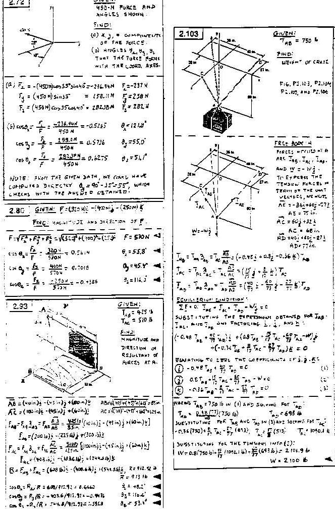
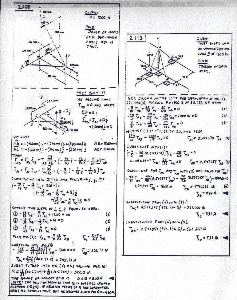
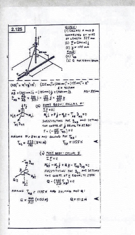
Sept.2-4th and 5th Lecture and first Quiz. Forces in Space. 3D equilibrium problems
Sept.4-Lecture 6. More on 3D Statics of a particle. Discussion of tension in cables. Direction cosines.
Sept.9-Lecture 7 and 8. Review of 2D and 3D statics problems. Introduction to vector products and definition of a moment. Second quiz.
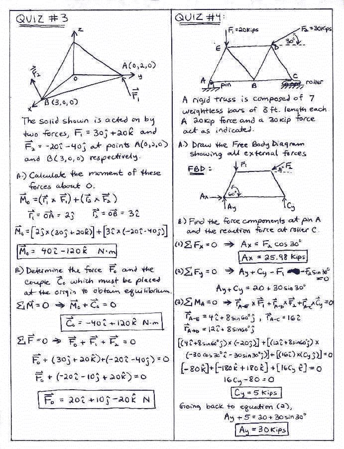
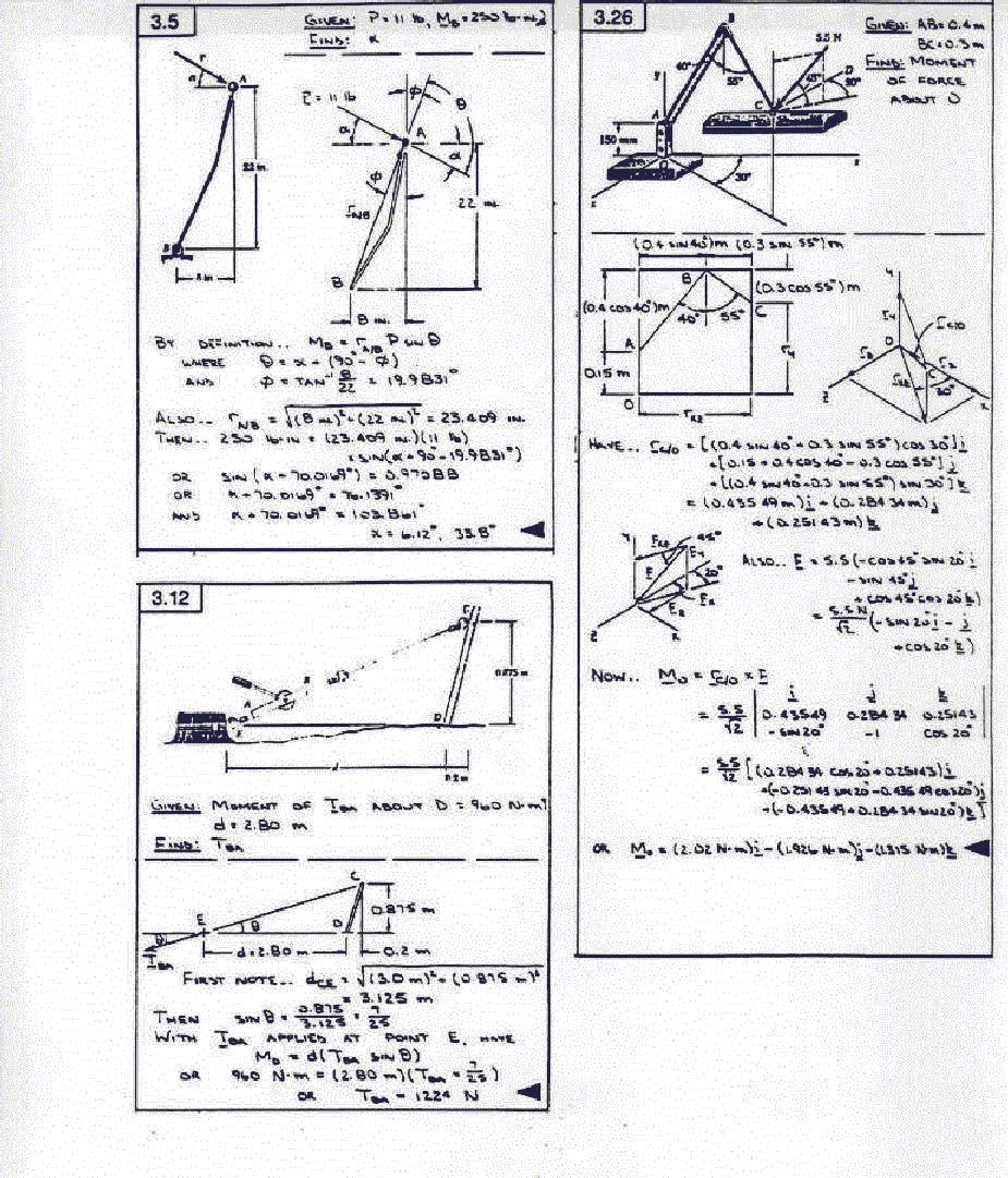
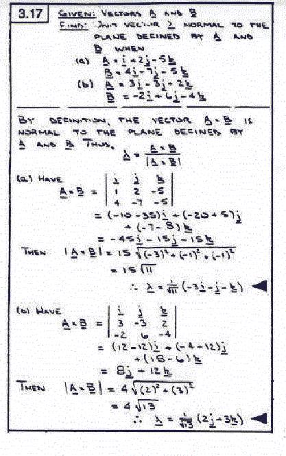
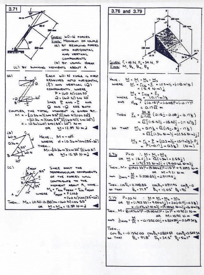
What are Moments and Couples ? A moment M is defined as the cross product between a position vector from the point about which the moment is taken and a force F, that is M=rxF. The simplest way to evaluate this product is via a three by three determinant in which the first row elements are the base vectors i,j and k. The second row consists of the position vector components and the third row are the force components. Thus r=2i+5j-3k and F=20i-40j+30k yields M=30i-120j-180k. The dimensions of M are length-force and so given in ft-lb in the US system of units and in met-newton in SI. A couple C consists of two equal but opposite forces F and -F separated by a position vector r. The couples value is simply rxF and will retain this same value no matter about which point the moments for the two forces are taken. The couple produced by F=10j acting at (3,0,0) and -F=-10j acting at (-3,0,0)is C=60k.
ALL THAT IS REQUIRED FOR STATIC EQUILIBRIUM OF A RIGID BODY IS THAT BOTH THE SUM
OF ALL FORCES ACTING ON IT BE ZERO AND THE SUM OF ALL MOMENTS( INCLUDING
POSSIBLE COUPLES) ACTING ON IT BE ZERO!
Sept.11-Lecture 9. Detailed discussion of couples and the effect of moving a force parallel to its line of action.
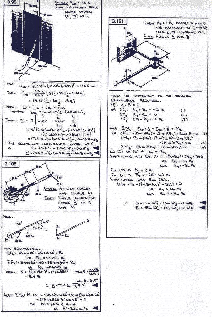
Sept.16-Lectures 10 and 11. Static equilibrium of rigid bodies. Equivalent force and couple systems. Third 15 min quiz covering forces, moments and couples.
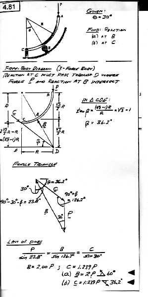
Sept.18-Lecture12. Two and three force bodies. Supports for rigid bodies.
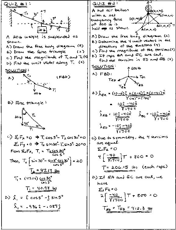
Sept.19,1997-Here are Solutions to Quiz 1 and 2:(Click to recover)
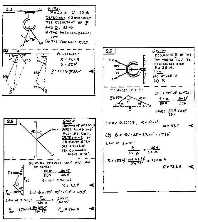
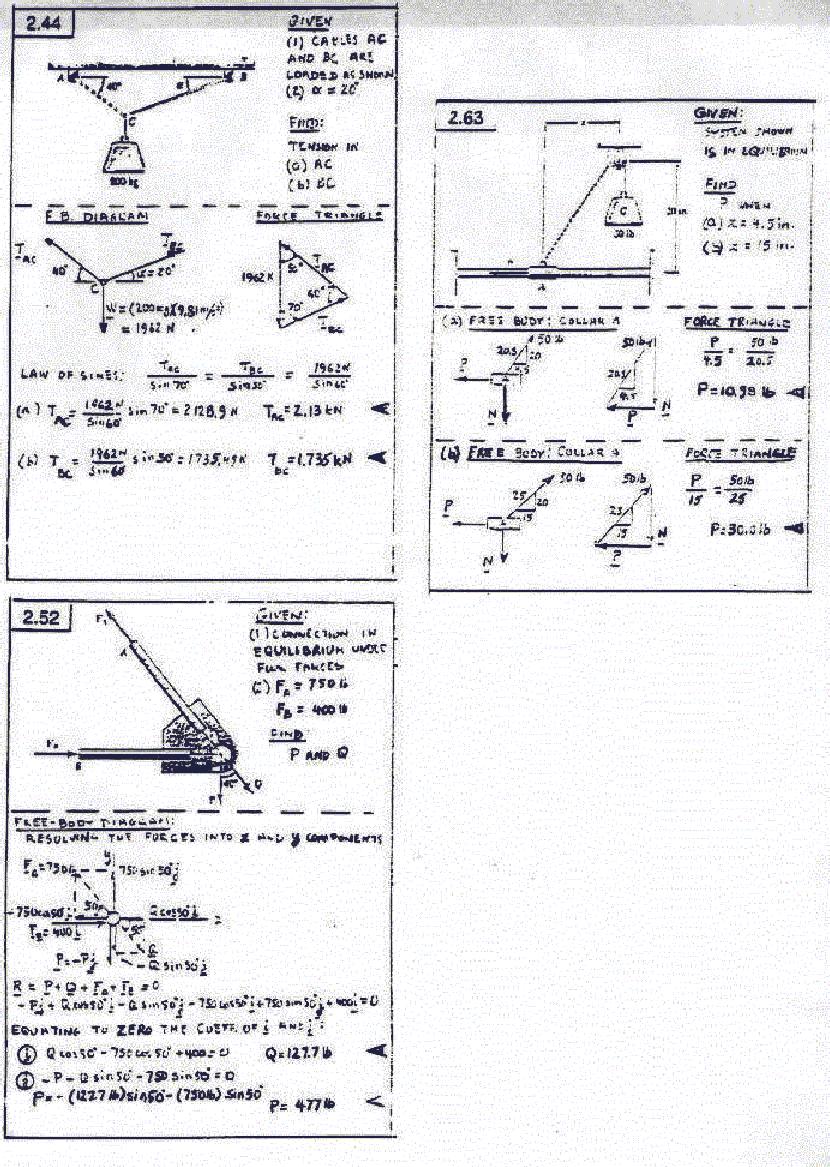
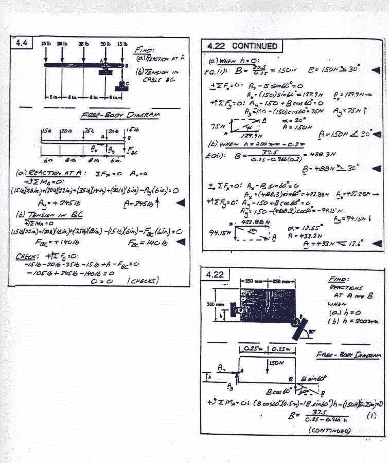
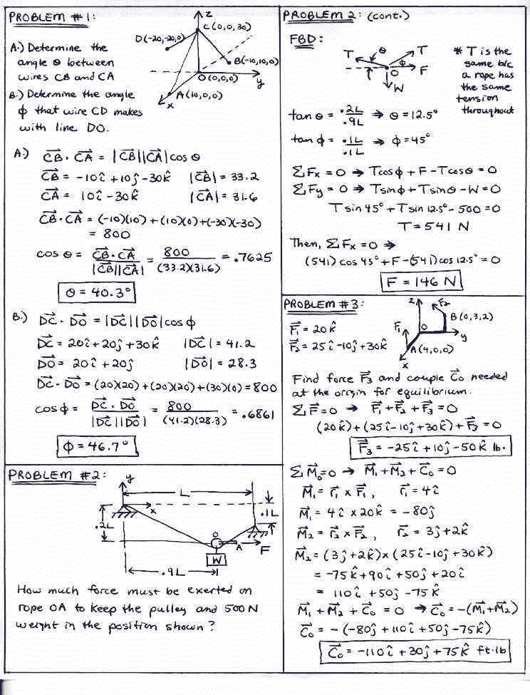
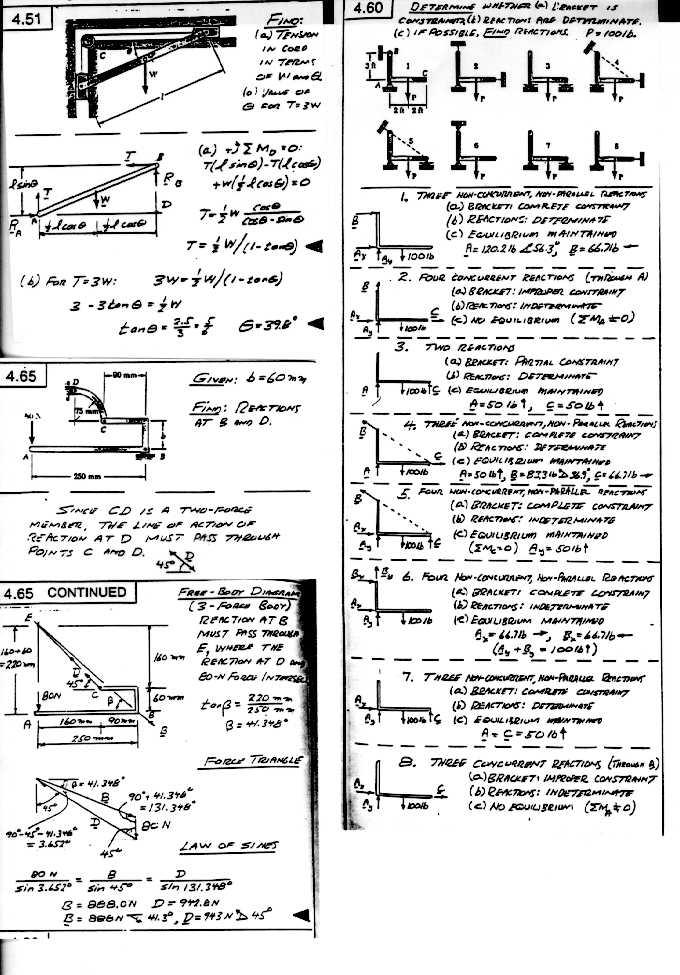
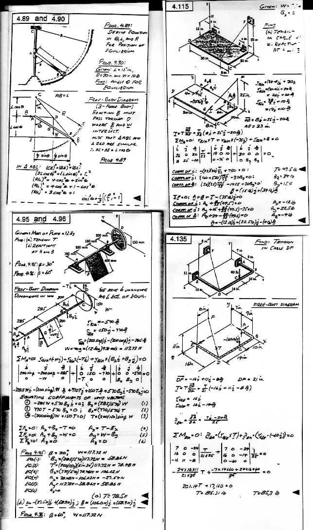
Homework Solutions(click to access):
Your first exam is scheduled for Wednesday evening Oct.1 during periods E2-E3(8:20pm-10:20pm). The class will meet in Carleton 100. It will be a common exam (also taken by the other statics sections)covering chapters 1 through 4. You can bring your pocket calculator and one 8.5"x11"sheet (filled with whatever formulas you wish) to the exam, but otherwise the exam is closed book.
Sept.23-Lecture 13 and 14-More on 2D and 3D static equlibrium of rigid bodies. Moments about specified axes . Also Quiz#4.
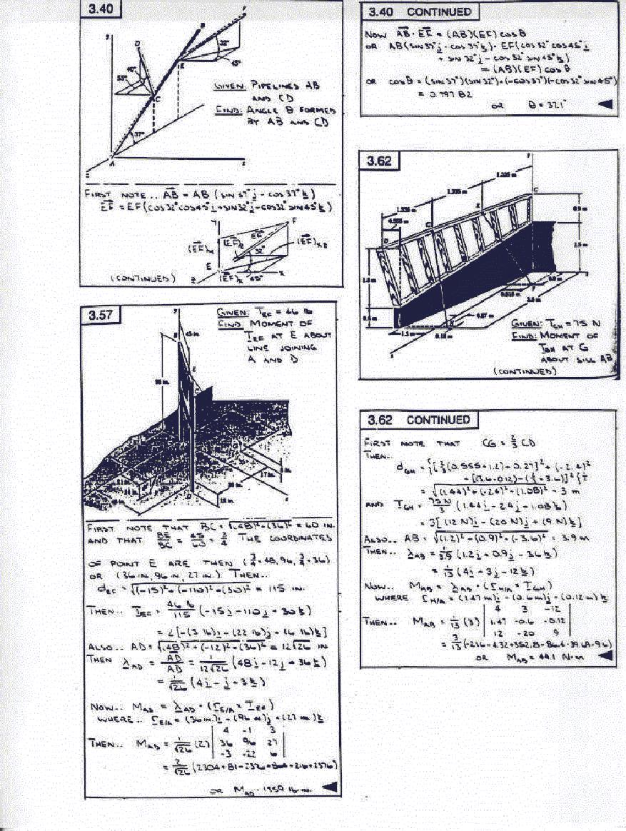
Sept.24-Moment About a Specified Line in Space: In solving some statics equlibrium problems one can often determine an unknown force(such as a tension in a rope attached to the body) by taking moments about a line passing through two points on the body at which there exist other unknown forces . By so doing you avoid having to solve for these other forces. To carry out this procedure requires knowledge of the moment about such a line. Let me demonstrate how this is done. Consider a cube extending over the range 0<x<1,0<y<1,0<z<1 . A force F1=10i+20j-30k acts at corner(x=1,y=0,z=1)and a second force F2=-10i+40k acts at corner (1,1,1). The moment produced by these two forces about the origin at (0,0,0) is M=(i+k)x(10i+20j-30k)+(i+j+k)x(-10i+40k)=20i-10j+30k. Now lets ask what is the projection of this moment on a line connecting the origin (0,0,0) and (1,1,0). We have this line defined by the unit vector r=(i+j)/sqrt(2) so that dotting it with M yields 10/sqrt(2). Thus the moment about the line becomes 5i+5j. Run through this calculation yourself using a sketch and also see if you can get this result another way. Note that we took the original moment about a point on the line chosen. Would you be able to obtain a moment projection along a given line if the original moment is taken about a point not on the line?
Solutions to Quiz 3 and 4:(click)
More Homework Solutions:
Sept.30-Review for first exam.
Oct.1,1997-First Exam this evening at 8:20pm(E2) in 100 Carleton auditorium . Two other statics sections will also be there so expect about 300 students .
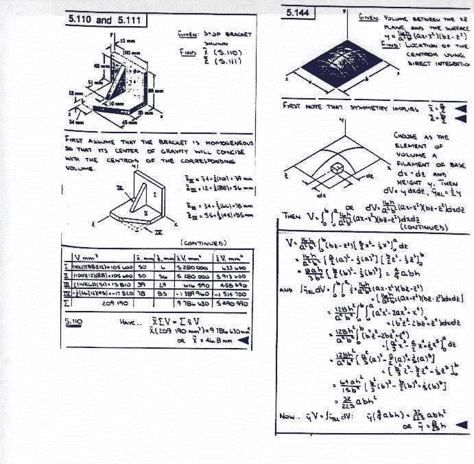
Oct.2,1997-Lecture 16. Distributed Forces. Introduction to Centroids and Center of Gravity.
Centroid for a Composite 2D System: To get some practice on finding the centroid of some 2D systems, consider the centroid of the block letter combination UF ( University of Florida ).What is x bar and y bar for this set up assuming both letters U and F are constructed of unit width rectangles and the two letters are separated by a unit distance? To make the calculation we break the U up into three rectangles. The first of these has corners at (-4,5), (-4,0),(-3,0) and(-3,5). The second has corners at (-3,0), (-1,0), (-1,1) and (-3,1) and the third corners at (-1,0), (0,0), (0,5) and (-1,5). Applying our composite body formula to these three rectangles yields a centroid for the U of xbarU=[xbarI*AI+xbarII*AII+xbarIII*AIII]/[AI+AII+AIII]=-2.00 and ybarU=[ybarI*AI+ybarII*AII+ybarIII*AIII]/[AI+AII+AIII]=13/6. Thus the centroid of U is at (-2.00,2.1667). Next look at F. Breaking it also up into three rectangles with the largest having corners at (1,0),(2,0),(2,5)and(1,5). The other rectangle has corners at (2,4), (5,4), (5,5) and (2,5) with the remaining square bounded by corners (2,2), (3,2), (3,3) and (2,3). One finds for the F the centroid is at (xbarF, ybarF)=(2.2778,3.16667). Finally combining the centroids for U and F yields xbar=[-2*12+(41/18)*9]/[12+9]=-0.1667 and ybar=[2.2778*12+3.16667*9]/21=2.5952. Thus the UF combination will have zero net moment about the point (-0.16667, 2.5952). I gave this problem several years ago as one of the problems on a statics exam and, if I remember correctly , about half got it right.
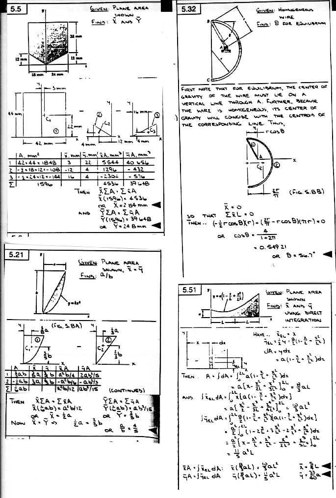
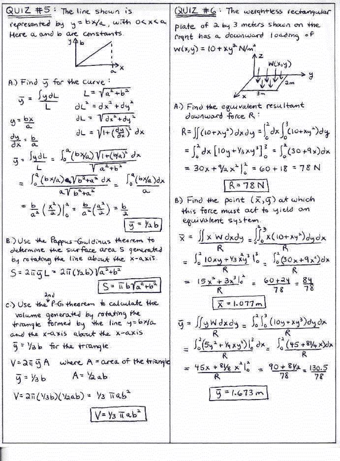
Oct.7,1997-Lectures 17 and 18. Centroids of Curves and Areas. The theorems of Pappus and Guldinus. Quiz #5 will not be until Thursday.
What are the Theorems of Pappus and Guldinus ? There are two theorems associated with the the names of Pappus of Alexandria( 290-350AD) and Guldinus( 1577-1643AD). The first of these states that "the product of the length of a curve and the distance moved by its centroid when the curve is rotated about an axis equals the surface area generated". As an example consider the half circle x^2+y^2=R^2, y>0 . It has length R*Pi and its centroid is at 2*R/Pi. Thus by the theorem, the surface area generated by rotating the curve about the x axis will be R*Pi*2*Pi*(2*R/Pi)=4*Pi*R^2, a well known result from calculus. Use the theorem to calculate the surface area of a toroid. The second of their theorems is that "the product of an area and the distance travelled by its centroid when this area is rotated about an axis equals the volume of the solid generated". As a demonstration of this consider the rectangle -a<x<a, 0<y<b rotated about the x axis. Its area is 2ab and its ybar is b/2. The volume generated is thus V=2ab*2*Pi*ybar=2*a*b^2*Pi. This agrees with the known volume of a cylinder of height 2a and radius b.
Oct.8,1997-The first exam has been graded. The average for our section was 82.6, with six perfect papers and one 18( lowest). Good show! Will hand stuff back tomorrow.
Oct.9,1997-Lecture 19-Quiz #5 and discussion on distributed loads and center of pressure.
Centroid of Composite Bodies with Holes: We have shown in class how the centroid of a 2D composite body is calculated by looking at the quotient of the sum of the products of xbar and subarea A divided by the total area to obtain the xbar of a composite body. When the body contains a hole then the procedure stays the same except that the subarea A (representing the hole )is preceded by a negative sign. To demonstrate take a circular disc x^2+y^2=4 into which is cut a square hole extending over 0<x<1,-1/2<y<1/2. Here by symmetry ybar is zero and xbar becomes [0*4*Pi-0.5*1]/[4*Pi-1]= -0.043228. So xbar is negative as expected .
Homework Solutions 10-12:
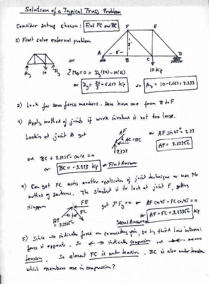
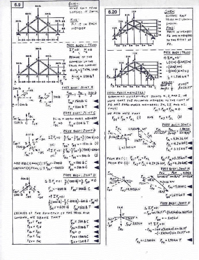
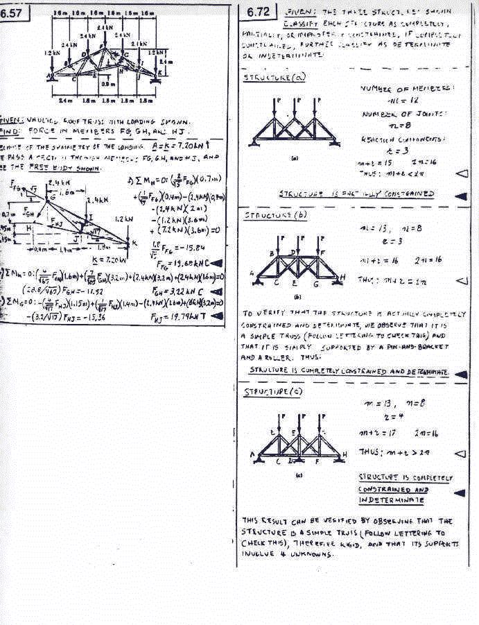
Oct.14, 1997-Lectures 20 and 21. Discussion of trusses. Method of joints and sections. Quiz #6 on distributed loads. To avoid asking you to solve homework problems on material not yet covered in class, all your assigned weekly homeworks can from now on be submitted on Thursdays.
Oct.16,1997-Lecture 22. More on trusses and discussion of frames.
Here is a typical worked out truss problem:(click)
More Quiz and Homework Solutions:
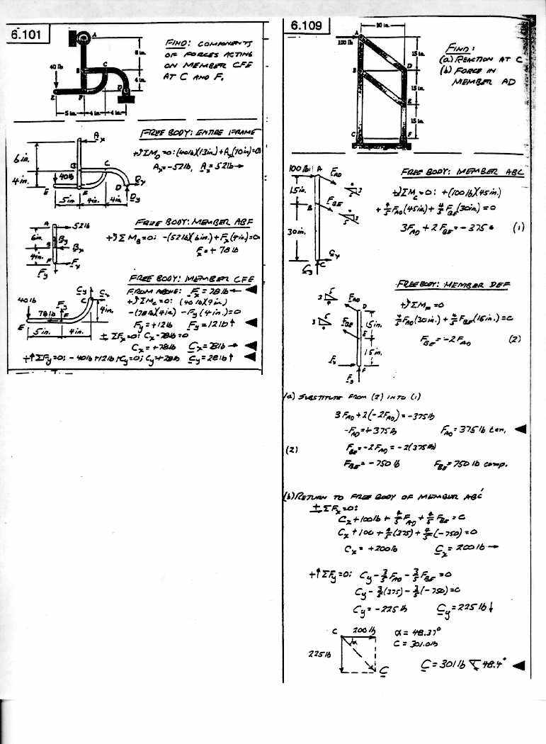
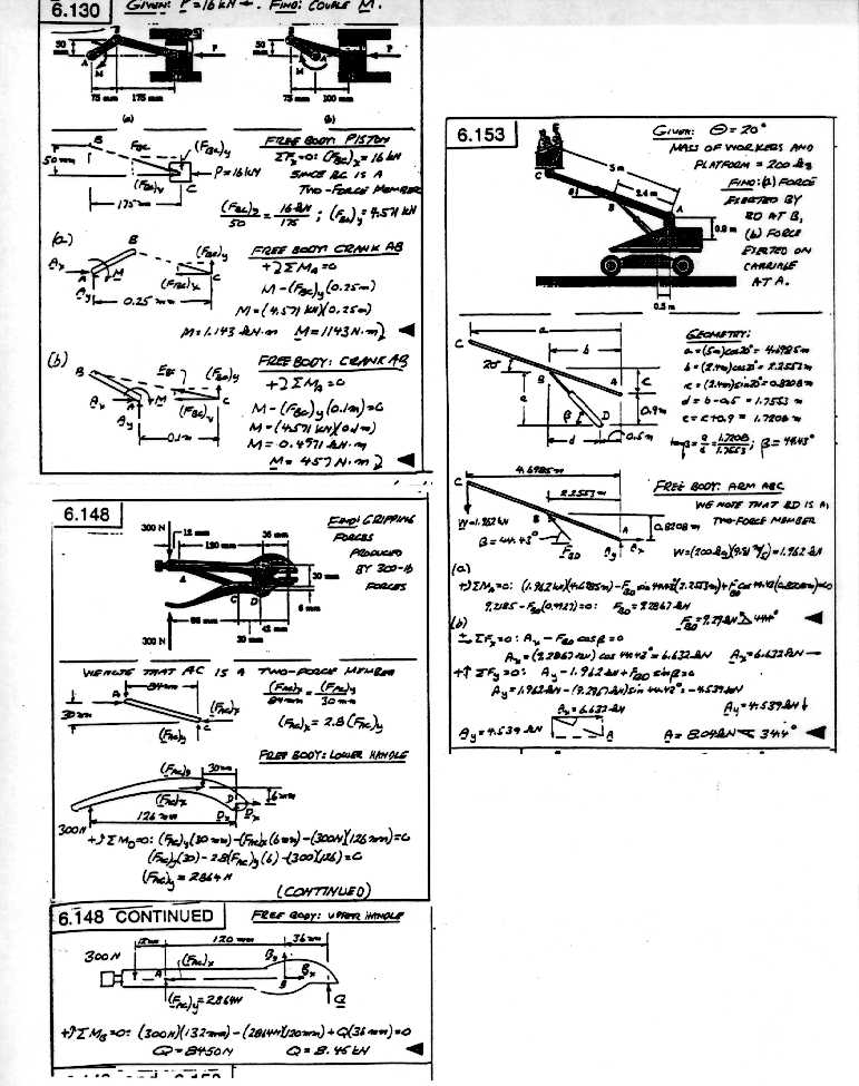
Oct.21,1997-Lectures 23 and 24. Discussion of frames and machines. Also Quiz #7 on trusses.
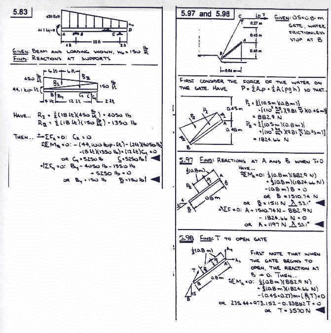
Oct.23,1997-Begin Chapter 7. Discussion of Shear and Bending Moments for Beams.
The Second Exam is scheduled for Tuesday evening Nov.4, with our section meeting in CSE A101 at E2(8:20pm). The format will be the same as last time with four out of five questions to be answered, however, this time two of the questions will be mandatory(that on centroids and that on shear and bending moments). The exam lasts two hours and is closed book with one 8.5"x11" sheet allowed. Chad Prazenica and I will be the proctors.
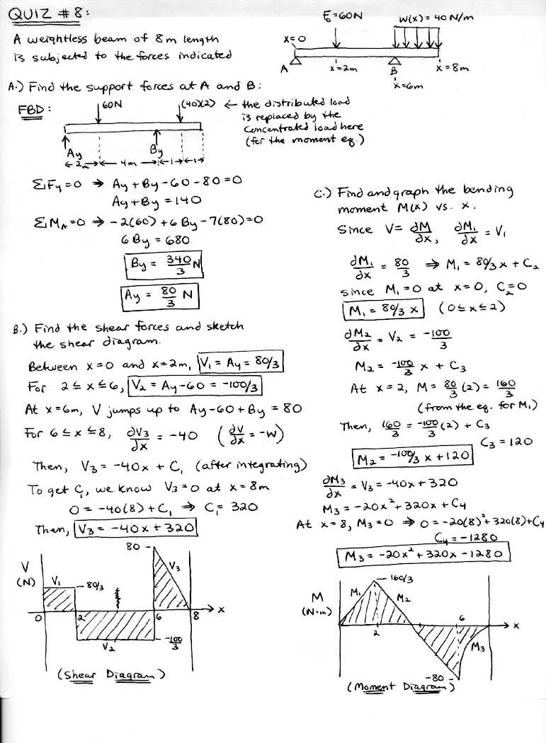
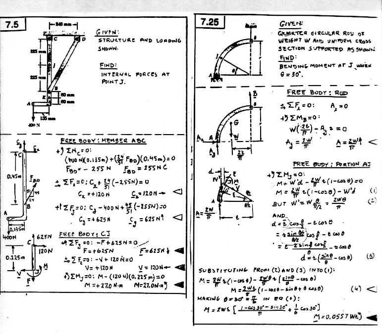
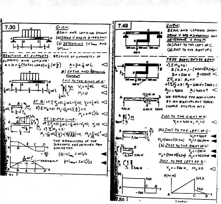
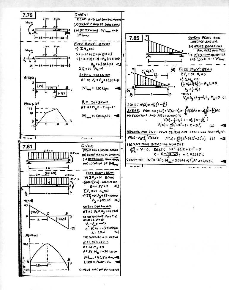
Shear and Bending Moment Diagrams: In class today we derived the basic equations dV/dx=-w(x) and dM/dx=V(x) for generating shear V(x) and bending moment M(x) diagrams for specified downward loading conditions w(x) along a bar. The value of V(x) equals the external force at the left end of the bar.This can be done by adjusting the constant in the solution for V(x). If the loading w(x) is constant then V(x) varies linearly with x , and when one has a downward point load of F at some point between the bar ends then V(x) drops by this amount there. Note from the above equations, that a constant value for V(x) corresponds to a linear variation in M(x). Likewise a linear variation in V(x) yields a quadratic variation in M(x). The value of M(x) at the left end of the beam is zero (unless there is a couple there such as for a cantilever). Placing a couple at some point along the bar does not change the V(x) variation, but does cause a jump in bending moment M(x) there equal to the value of the couple. The jump is up for a clockwise couple and down for a counterclockwise acting couple. A hook is equivalent to a point force plus a couple acting at the attachment point. It is usually a good idea to draw the bending moment diagram directly below the shear diagram as the slope of M(x) just equals V(x), so that a direct comparison is possible. Work out the shear and bending moment diagram for a 10 ft weightless bar supported at its ends and having a 60 lb downward point force acting at x=4 ft plus a counterclockwise couple of 20 ft-lb acting at x=6ft.
Oct.28,1997-Lectures 26 and 27. More on Shearing and Bending Moment Diagrams. Also brief discussion on cables subjected to concentrated loads. In addition we will have Quiz#8 on shear and bending moments.
Shape of a Suspension Bridge Cable: Yesterday we touched briefly on the shape a cable will assume when subjected to point loadings.We showed that under such conditions T cos(theta) was a constant at equilibrium and the cable shape between two neighboring point loads was a straight line. Now the next question which arises is what will be the cable shape if we allow the loading per horizontal distance to be constant and the distance between loads to approach zero. This is precisely the condition one has with a suspension bridge carrying a roadway of constant weight per length. Taking a little chunk of the cable , whose left end is horizontal and where the tension is T and whose right end has tension T + dT at angle theta to the horizontal, one has from a force triangle consideration that the slope dy/dx of the cable is just equal to the ratio of w dx to T. Also since dx is a very small quantity, this means that y"=w/T which integrates to y=[w /2T] x2. Thus , the shape of a suspension bridge cable under uniform horizontal loading will be a parabola. Note that a cable hanging under its own weight (so that one has constant loading per unit length of cable) results in a hyperbolic cosine shape known as a catenary curve. The catenary is also encountered in certain calculus of variation problems involving surface area minimization.
Oct.30,1997-Review for Exam #2
Homework Solutions Numbers 16-19
Nov. 4, 1997- More review to get ready for tonights
exam.![]()
Have lost the rest of this page through Dec 12th due to publishing without noting a transfer interruption. If someone has made a printout of this WEB page earlier please send me a copy so that things can be restored.
![]()
