
Page first set up-Sept 1,
1996
Latest Update-July 28, 2016

 EGM3400 EGM3400
ENGINEERING
MECHANICS-DYNAMICS
Instructor:
U.H.Kurzweg
|
INTRODUCTION:-The material presented below is an an
extended outline for a 2 credit dynamics course( EGM 3400)
which I have taught here at the University of Florida on and
off for nearly three decades. This course and my other
classes in mechanics and applied mathematics have won
numerous teaching awards including five from the College of
Engineering and three University wide awards. We meet twice
a week for a total of 21 contact hours and the book we have
been using most often is that by
R.C.Hibbeler's,"Engineering Mechanics-Dynamics". You can contact me anytime at kurzweg@ufl.edu .
Click HEREfor the COURSE OUTLINE , TEST AND GRADE
DETERMINATION METHOD.
Lecture 1-
Introductory Remarks. Velocity and Acceleration. Curvilinear
Motion. Simple Harmonic Motion. Motion of a Projectile.
Go HERE to see a
schematic of the Projectile Problem and it's Solution.
Lecture 2- Kinematics in Cylindrical Coordinates including
discussion of the three Base Vectors used. Radial and Angular
Acceleration. Motion along a Spiral. Normal and Tangential
Coordinates. Relative position and velocity.
A PROBLEM IN RELATIVE
MOTION: In class today we
discussed, among other things, the kinematics of particles and
their absolute and relative motions as described by position
vectors. Click HERE to see
a graph for the solution of the two vehicle problem based on
relative velocities.
MOTION ALONG A SPIRAL
DESCRIBED IN POLAR COORDINATES: In
addition
to describing the motion of a particle in cartesian
coordinates, it is often to advantage to express things in
polar or cylindrical coordinates.
In polar coordinates one
has the position vector r=r*e[r] with velocity
v=(dr/dt)*e[r]+r*d(e[r])/dt. Here e[r] is the unit base vector
in the radial direction and one also has the unit base vector
in the theta direction of e[theta]. The two base vectors are
orthogonal to each other so that the dot product between them
vanishes. Simple geometry also shows that d(e[r])/dt=e[q]*wand d(e[q])/dt=-e[r]*w,
where w=d(q)/dt.
Using these last identities one finds that v=dr/dt*e[r]+r*w*e[q] and
the acceleration in polar coordinates becomes A={d^2r/dt^2-r*(w)^2}*e[r]+{2*dr/dt*w+r*d(w)/dt}*e[q].
Click HERE to see a specific calculation for particle
motion in polar coordinates leading to the famous spiral of
Bernoulli.(Bernoulli was so proud of this spiral that he had
it engraved on his tombstone. Click HERE to see
me pointing to it during a recent visit to Basel,
Switzerland). Extention to 3D problems will involve
cylindrical coordinates which have the extra base vector e[z]
pointing in the z direction.
TANGENTIAL AND NORMAL
COORDINATES: An alternative
method for expressing velocities and accelerations of a
particle moving along a curve is by the use of unit tangential
e[t] and unit normal e[n] base vectors. For this type of
description the velocity is simply V=v(t)e[t] and the
acceleration is A=dV/dt=(dv/dt)e[t]+(de[t]/dt)v . But
de[t]/dt=d(icos(q)+jsin(q)/dt which by use of the chain rule
reduces to A=(dv/dt)e[t]+(v^2/r)e[n].
Here r is the radius of curvature
of the curve which generally changes with position and in 2D
is given from calculus by r=(1+y'^2)^(3/2)/y".
Click
HERE to see
a calculation for the acceleration of a particle moving with
constant speed along a cubic curve.
Lecture 3-Kinetics
of Particles.(Chapter 13 of Hibbeler) Newton's Laws of Motion.
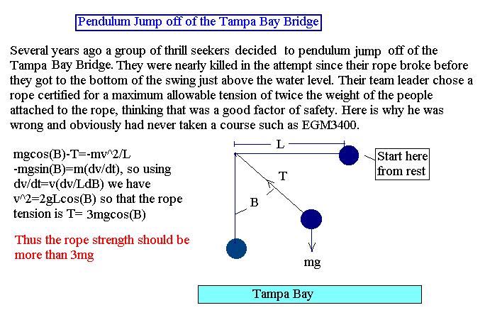
The role of Weight and Thrust on the Acceleration of a Mass
according to Newton's Second Law. Distance a hockey puck will
slide. Pendulum jumping off of the Tampa Bay Bridge. Atwood
machine. Geosynchronous Satellite.
PENDULUM JUMP:(Click Here)
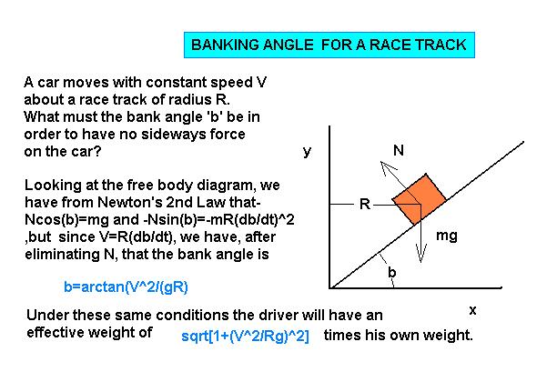
BANKING
OF A RACETRACK:(Click Here)
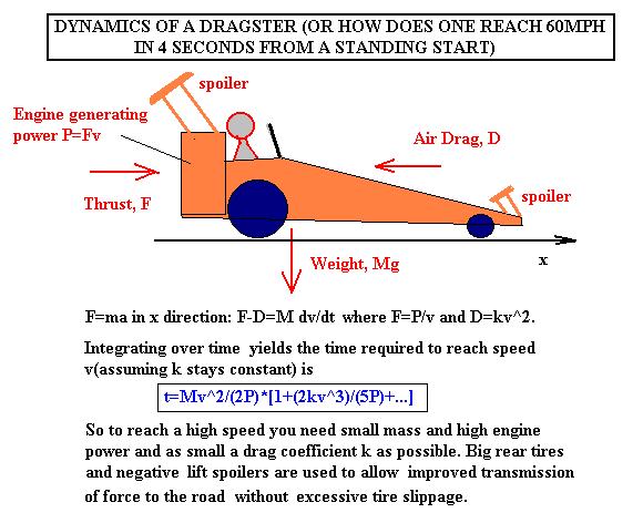
KINETICS OF A DRAGSTER:
As another example of a particle dynamics problem consider the
time it takes for a dragster to accelerate from 0 to
60mph. Click HEREto see the mathematical
development of this problem based on F=ma. Note that the time
to reach a speed v for a car of mass M and power P is at
least t=Mv^2/(2P). If I plug the numbers of P=500HP and
W=3600lb (with driver)applicable for the 10 cylinder Dodge
Viper, the minimum time to reach 60mph will be 1.57 sec. The
latest issue of Car and Driver gives the actual value for the
Viper to be 4 seconds even. The factor of two difference
clearly has to do with presence of air resistance at higher
speeds and transmission losses among other things. Nevetheless
the formula clearly shows that one needs small mass and high
engine power to achieve large accelerations. For my 1967
Camaro rated at 275HP the formula gives a time of 2.62sec
which is again shorter by an approximate factor of two to
the six seconds it actually takes me to reach 60
mph. Can you explain, in view of the above formula , why a
bicyclist will beat an automobile everytime for the first few
feet after a standing start?
Lecture 4-More
applications of F=ma . Mass-Spring System. Geosynchronous
Satellite. Determination of Escape Velocity. Sorry about
the poor acoustics of todays lecture in NEB100, have contacted
instructional resources to get the PA system fixed.
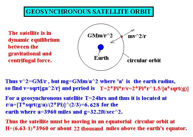
PERIOD OF A SATELLITE IN
CIRCULAR ORBIT: A simple
calculation involving a polar coordinate description is the
determination of the orbit of a satellite of mass m moving
in a circular orbit about a heavy mass M. The attractive
force on such a satellite is GMm/r^2, where r is the
distance between the mass centers according to Newton's Law
of Universal Gravitation. This force is balanced by
the satellite mass times its radial acceleration, which for
a constant radius circular orbit, is just mv^2/r. One thus
has that the orbital velocity must be v=sqrt(GM/r).
But GMm/a^2=mg, where 'a' is the radius of the large mass
and , for the earth, g=9.81m/s^2=32.2ft/s^2. So
v=a*sqrt(g/r) and the satellite period becomes T=2*p*r/v=(2*p*r^1.5)/(a*sqrt(g)).
For
a near earth satellite one has that r is approximately 'a',
so that there the orbital period becomes 2*p*sqrt(a/g), which turns out to be
about 1hr 24min for the case of a near earth satellite where
a=6378km=3960 miles. What should be the approximate
orbit time of the moon located an average distance of some
239,000 miles from the earth center? If you click HERE you
can see the calculation which gives the height above the
earth's surface a geosynchronous satellite must be placed in
order for it to have a period of one day and hence appear
stationary.
SOME EARTH DIMENSIONS:
I noticed in yesterdays discussion on earth dimensions that some
of you were not very familiar with what is the precise value of
the earth's radius. Lets quickly go over this and some other
earth properties. The earth's equatorial circumference is 24,902
miles=40,075 km, so that its equatorial radius is R=3963.5
miles=6,378 kilometers. Because it spins at an omega of 2p/(24 x 3600)=7.2722x10⁻⁵
rad/sec, any point on the equator moves to the east(relative to
the earth center) at 24,902/24=1037.6 miles/hr. At a latitude of
theta this number drops by cos(q), so
that in Gainesville, which is at about 30 degrees latitude , we
are moving to the east at 898.6 mph. This eastward rotational
speed is used to advantage when launching an object into orbit
from the cape here in Florida. A nautical mile corresponds to
one minute of longitude along the equator and thus equals
24,902/(360x60)=1.15 miles=6076 ft. Note that , due to the spin
of the earth , the near spherical shape of the earth is slightly
flattened at the poles so that the polar radius is actually some
13.32 miles less than its equatorial value. If the earth were
spinning at w=sqrt(g/R)=sqrt[32.2/(3963.5
x
5280)] x 3600=4.47 rad/hr or 17.06 revolutions per present earth
day , a mass sitting on the equator would become weightless
because the downward gravitational force would then just be
cancelled by the outward centrifugal force , just like for a
satellite. We also have that GMm/a^2=mg, where a is the earth
radius , G=[6.6754 plus or minus 0.0005]x10^(-11) is the
universal gravitational constant in SI units, M is the earth's
mass and m a test mass sitting at the earth's surface. From this
last equality one sees that the earth's mass equals
M=ga^2/G=9.81x(6.378x10^6)^2
/(6.6754x10^-11)=5.97x10^24 kg as first found over 200
years ago via the famous torsion fiber experiment for measuring
G by Henry Cavendish(1798).
Lecture 5-Newton's
Law of Gravitation and Orbital Mechanics. Kepler's Laws of
Planetary Motion. Abhelion, Perihelion and Eccentricity. Other
sample problems involving particle kinetics including the
acceleration of a dragster and the motion of a mass spring
system down an incline with friction.
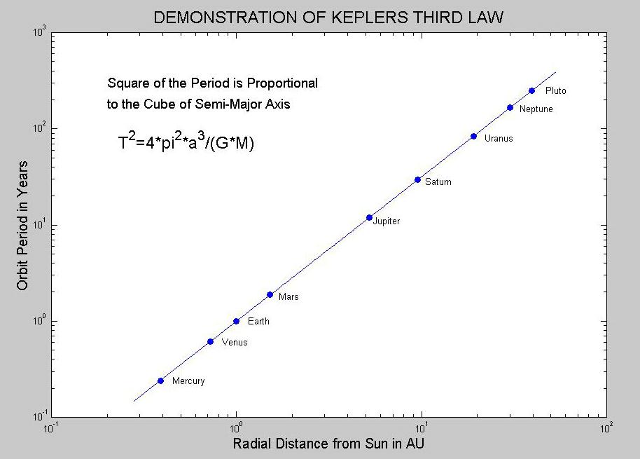
CALCULATING THE ORBIT OF
A PLANET: One of the most
famous problems in all of mechanics was Newton's analysis of
the orbit of planets based on his Universal Law of
Gravitation. Kepler, using observational data of Tycho Brahe
, had already determined several years earlier that the
orbits of planets about the sun were in the form of ellipses
of very small eccentricity with the sun at a focus(Kepler's
First Law), that the trajectories swept out equal area per
time(Kepler's Second Law), and that the square of the
orbital period is proportional to the cube of the semi-major
axis(Kepler's Third law). You can see a summary of Newton's
analysis for the earth-sun system by going HERE You can also see a beautiful confirmation
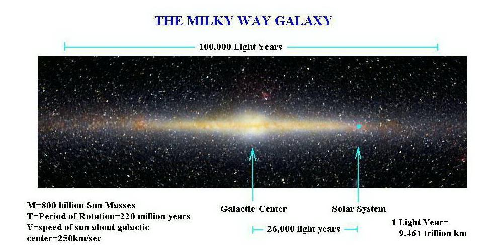
of Kepler's Third Law by clicking HERE. An
interesting (imaginary)view of our galaxy and its known
properties is shown HERE. We can in addition use these laws to
calculate the distance a geosynchronus satellite must be
placed above the earth's equator. Knowing that the time for
a near-earth satellite to go once around is 1.4 hrs, a
geosynchronus satellite, which has a period T= 24 hrs and
obeys Kepler's third law, must be at 'a'=(24/1.4)^(2/3)=6.6
earth radii from the earth's center or (a-1)*3960=22,200
miles above the earth's surface.
DETERMINING THE MASS OF THE
SUN: Have you ever wondered how
astronomers are able to know the mass of various astronomical
objects? The determination is really quite simple and just
based on the assumed validity of Newton's universal Law of
Gravitation F=-[GMm/r^2] everywhere in the universe. Take for
example the sun's mass. It is found by balancing the
attractive force between the sun and earth with the earth
centrifugal force in its essentially circular orbit. I show
you HERE the calculation which yields a mass of
M=1.98x10^30 kg. Note, since one usually does not recall the
precise value of the universal gravitational constant G, it
becomes convenient to use the identity Gm=ga^2, where m is the
earth mass , g the acceleration of gravity, and 'a' the earth
radius.
Lecture 6-Work-Energy
Principle.
Conservation of Energy. Energy stored in a Spring. Gravitational
Potential.
WORK-ENERGY PRINCIPLE
APPLIED TO A SLIDING MASS-SPRING SYSTEM: The Work-Energy Principle for a particle states
that the sum of the work done on the particle equals the
change in its kinetic energy. To demonstrate this principle
consider the problem of releasing a mass attached to a linear
spring on a rough incline. Here the spring work is
Ws=-(1/2)kx^2, the work against gravity is +mgxsin(q), where theta is the angle of the
incline, and -(m)mgcos(q)x is the friction work with m the coefficient of friction and x the
distance down the plane the mass has slid. Details of the
problem are found HERE
Note that the mass
first speeds up, reaches a maximum speed and then slows down
and comes to rest before reversing its motion. It is important
to remember that the friction work always acts to reduce
the kinetic energy and this explains why the present mass will
never return to its starting point.
THE SIMPLE PENDULUM
ANALYZED BY THE ENERGY METHOD: For
non-dissipative dynamical systems one has the well known fact
that the sum of the kinetic energy(T)and potential (V)energy
is a constant. Lets apply this conservation law to a simple
pendulum of mass m held by a weightless rod of length L.
Measuring the potential energy from the bottom of the swing we
have V=mgL[1-cos(q)] as its value
at angle q with respect to the
vertical. The corresponding kinetic energy is T=mv2/2.
Neglecting all friction, we then have , from the conservation
of energy law, that Const=[gl(1-cos(q)+v2/2].
Thus if we start the pendulum at rest from its inverted
position at q=p
, its speed at the bottom(q=0)of
the swing will reach the value of v=2sqrt(gl). At the same
time if one started the pendulum at the bottom with a speed
greater than this last value, it would go over the top and
continue to rotate about the pivot point instead of
oscillating about it. This behavior can be well described by
looking at the pendulum's phase plane trajectory with q lying along the horizontal axis and
v/sqrt(2gL) along the vertical axis. Click HEREto see the phase plane diagram for the simple
pendulum.
G FORCES ON ROLLERCOASTER
RIDES: Another interesting
dynamics problem treated by energy methods is that of
determining the g forces experienced at the bottom of the
first drop in some of the new rollercoaster rides. These
accelerations, can become considerable and approach
values comparible to those experienced by fighter pilots and
astronauts. Lets quickly show the analysis and take as
our model the newly opened Millenium Force steel rollercoaster
at Cedar Point in Sandusky, Ohio. It has a 300 ft drop and
extends for some 6600 ft. We represent the track height in ft
as y=300*cos(0.004*x))^2*exp(-0.002*x) and look what happens
in the first 2000 ft of horizontal distance. We know from the
conservation of total energy that the speed is
v(x)=sqrt[2*(300-y(x))] , since (1/2)mv^2=mg[300-y(x)]. Also
the centripetal acceleration will be v^2/R, with
R=[1+y'^2]^(3/2)/y" from calculus. Thus the centripetal
acceleration(and hence a corresponding centrifugal force per
mass) measured in units of g will be
2(300-y(x))*y"(x)/[1+y'(x)^2]^1.5. A plot of both the assumed
track and the normal acceleration experienced is shown HERE. Note
that in our model the maximum centripetal acceleration is 3g
at the bottom of the first drop and becomes -1g at the
top of the next rise. You have to add a downward acceleration
of 1g onto these results due to the earth's attraction on any
body at the earth's surface. The speed at the bottom is about
140ft./sec. The Millenium coaster people claim their
coaster reaches 92mph=135ft/sec. This slightly lower value
must be due to drag forces not included in our conservation of
energy calculations. You probably heard about a lady recently
being killed on one of these rides in California due to a
burst blood vessel in her head. Healthy individuals can
withstand accelerations as high as 7g before blacking out and
rollercoasters are designed to not exceed 3g. One should also
recognize that in addition to the centripetal acceleration
considered here there will also be an acceleration along the
track given by v*dv/ds plus a sideways acceleration if
the rollercoaster makes turns.
IMPACT VELOCITY OF AN
ASTEROID OR OTHER CELESTIAL BODY HITTING THE EARTH: In discussing the conservation of energy law
for conservative systems, we asked the question "With what
velocity will a rock of mass m released from rest at distance
H above the earth's surface hit the earth?". Neglecting all
frictional losses, one simply has that the sum of
the potential energy V plus
kinetic energy T at the beginning and end of the trip are the
same. We thus have that [0-GMm/(R+H)]=[mv2/2-GMm/R].
This evaluates to v2=2gR[1-1/(1+H/R)]
, when using the identity GM=gR2.
If we now start the rock from rest at H=R above the earth's
surface, it will impact with v=sqrt[gR]=4.91 miles/sec since
the earth radius is R=3960 miles and the acceleration constant
has the value of g=32.2 ft/sec. You can see from this example
the tremendous
amount of kinetic energy
which would be carried by a large asteroid impacting the earth
and why it is not implausible that such a collision might have
led to the demise of the dinosauers. Note that a rock starting
from rest at infinity would impact the earth with the escape
velocity of v=sqrt(2gR)=6.95 miles/sec=11.18 km/sec. Meteor
impact speeds (before being slowed by the
atmosphere) can actually be
much higher than this last value and range up to 72 km/sec.
This last value would result from a head on collision and is
derived by adding the sun's escape velocity at earth distance
plus the earth's orbital speed around the sun of about 30
km/sec [i.e. 30 +30 sqrt(2) = 72]. A major problem the space
agencies around the world are running into is space junk.
There presently are thousands of pieces of man made junk from
earlier orbit missions floating around the earth at orbital
speeds of about 11.18/sqrt(2)=7.9km/sec. The larger
pieces(greater than 1meter) can be tracked by radar and so can
be avoided, but pieces between a few mm to several cm in
dimension pose a real hazard to astronauts in near earth
orbit(see the June 2002 issue of Science). A cheap way to
install a shield against ICBMs would be not try to shoot down
an incoming missile with another one but rather to deploy(
from orbiting satellites) millions of retro-orbiting small
particles into the path of the incoming ICBMs. The result
would be a very effective space flak. However, a major
drawback of this approach would be that one has no kown
economic way to remove these particles (and also other space
junk)once the missle threat is over.
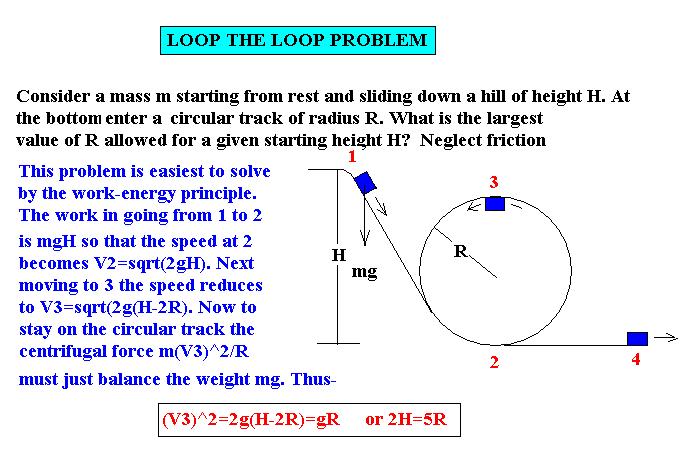
Lecture 7-More on
the Work-Energy Principle. Conservation of Energy
T+U=Const in the absence of friction. Pendulum and Satellite
Motion. Phase plane concepts. Click HERE to see the Loop the Loop
problem.
PARTICLE FALLING THROUGH A SHAFT
DRILLED THROUGH THE EARTH: Another very good application of the conservation
of energy for a mass m is to determine the time, speed
and acceleration of this mass as it is dropped through a
straight-line shaft drilled through the earth between
two points A and C on its surface. Go HERE for
a discussion of this problem. We show that the period of
the resulant SHM motion will always be the same
regardless of the off-set position d of the shaft
relative to the earth's rotation axis.
Lecture 8-Review for First Hour
Exam-There will be 3 out of 4 questions to answer. Exam
will be during the class period. It will be closed book but you
can bring one 3" x 5" card. You are responsible for the
material in the Hibbeler book covered in our first seven
lectures plus all material covered in class , shown on this WEB
page, and encountered while doing your homework.
Lecture 9-FIRST HOUR EXAM.
Lecture 10-
Impulse-Momentum Principle. Conservation of Linear Momentum in
Collisions. The Coefficient of
Restitution. Bouncing Balls, Gun Recoil, and Car Wreck.
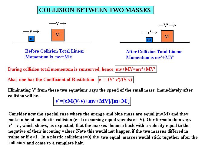
DEMONSTRATION OF THE
CONSERVATION OF MOMENTUM LAW: We
have shown you in class that the total momentum is conserved
during the collision of bodies. Lets now apply this law to
two masses m and M moving along the x axis with speeds v and
V, respectively. If v>V and m follows M, the two bodies
will eventually collide . We want to find their speeds after
this collision. Applying the conservation of linear momentum
we have mv+MV=mv'+MV', with the primes indicating the speeds
after collision. To make this problem soluable we need a
second condition, namely, that the coefficient of
restitution equals e=-(V'-v')/(V-v).
Solving for V' from this last equality and plugging into the
momentum conservation result, then yields v'=[v(m-eM)+MV(1+e)]/[m+M].
This is an interesting result. It shows, for example, that
if we have an elastic collision(e=1)
and the two masses are equal, that v'=V and V'=v. So if V=0
then little m stops completely and M=m travels forward with
the original speed v of m. The billard players among you
will recognize this fact. Note that the energy loss in a
elastic(e=1) collision is zero,
but that there will be losses whenever e<1
and
that this loss becomes large during plastic collisions where
e=0. Click HERE to
see a pictoral development of the collision formula.
Lecture 11-More on
Impulse-Momentum Principle. Ballistic Pendulum. Oblique
Collisions for specified values of e.
Angular Impulse and Conservation of Angular Momentum. Systems of
Particles. Force of a Water Jet and functioning of a Rocket. Go HERE to see an
interesting animation of oblique billiard ball collisions. You
can vary the initial conditions and the mass ratio. Go HERE to view a
pdf file in which I show you the mathematical details of an
oblique collision process.
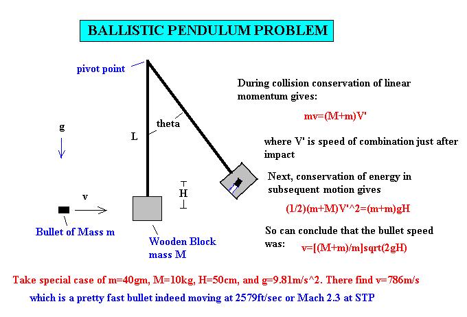
THE BALLISTIC PENDULUM:
An interesting application of the
conservation of momentum law coupled with the conservation
of energy concerns the ballistic pendulum. The
ballistic pedulum is a device used to measure the speed of a
bullet by noting how high a woodden block attached to a
swing arm will rise from a position of rest after the
bullet becomes embeded. The analysis consistes of a two part
consideration . First during initial impact the linear
momentum is conserved. Second after the bullet is embeded in
the block one has a conservation of total energy where the
kinetic energy at the bottom is entirely converted to
potential energy at the top of the subsequent swing. Click HEREto
see the details of the analysis.
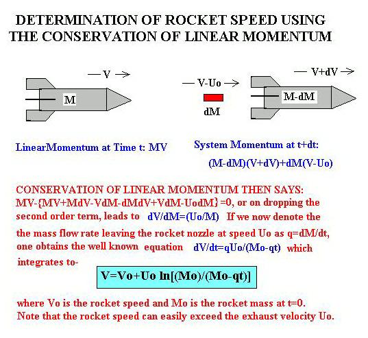
ROCKET PROPULSION: An interesting application of the Impulse
Momentum Principle is the determination of the speed of
a rocket as a function of time.HERE
is the analysis. The very small payload boosted
to orbital speed compared to the initial launch
mass(even with staging) shows you, for example, why you
won't be taking vacations in earth orbit until someone
comes up with a much cheaper method than the use of
rocket propulsion using chemical fuel.(I take back
this comment I made several years ago, since in May of 2001
Dennis Tito, a wealthy eccentric businessman from
California, did go up into earth orbit at the cost to him of
some twenty million dollars, or about $100,000 per pound.
The russians took advantage of him since NASA claims they
can launch things at ten times less per pound. Costs with
chemical fuel launches are not expected to ever drop much
below about $1000/lb for orbiting a body, although the
actual kinetic energy equivalent which must be expended for
a mass m in orbit is only T=(1/2)mv^2=mgR/2, since the near
earth orbital speed is v=sqrt(gR), with R equal to the earth
radius. Thus each kilogram in a near earth circular
orbit has about 31 megajoules of kinetic energy which is
close to the 44 megajoules chemical energy contained
in a kilogram of gasoline. It is the need to boost the
heavy peripheral equipment, including rocket motors , fuel
tanks, etc , to high speeds which makes the chemical launch
process expensive. For example, the space shuttle
requires some 4 million pounds of solid and
liquid fuel for a ground launch from the cape . There ought
to a much less expensive way to put something into orbit,
but so far no one has come up with a good alternative.)
Lecture 12-Completion of discussion on Impulse Momentum
Principle, Systems of Particles. Forces of a Water Jet
on a Turbine Blade. Angular Impulse and Conservation of Angular
Momentum.
FORCE ON A TURBINE BLADE: Another interesting application of the impulse
momentum principle is the turbine blade problem shown in the
accompanying figure( Click HERE). We
know from the impulse momentum principle that the force
exerted on a body equals the net momentum flux out of a system
bounded by a control volume. For the turbine blade we have an
incoming fluid jet which breaks up into two parts at the
turbine blade and shoots two streams out at angle theta with
respect to the axis of the incoming jet. The mass flow
rate in this case is dq/dt=rAoV
and the reaction force Fx=(dq/dt)*V*[1+cos(theta)]. Note such
forces can become quite large and can be used to advantage in
hydroelectric generating plants. Cavitation damage remains a
major problem for water driven turbine blades.
FAMOUS PEOPLE IN THE
HISTORY OF MECHANICS: As a small diversion from our
dynamics discussions, I thought you might be interested in seing
some of the most famous individuals historically associated with
mechanics. Click HERE to see a thumbnail gallery.
Contributions of these and other scientist and mathematicians
can be found at
http://www-groups.dcs.st-and.ac.uk/~history/BiogIndex.html
Lecture 13- Kinematics of Rigid Bodies. Angular
Velocity and Angular Acceleration. Velocity and Acceleration
at any Point on a Body in Translation and Rotation.
Crank-Piston Mechanism.
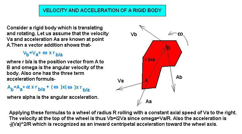
VELOCITY AND
ACCELERATION AT ANY POINT OF A ROTATING AND TRANSLATING
RIGID BODY: Consider a rigid
body containing two points A and B. We can relate the
velocity and acceleration at these two points to each other
by a simple vector addition involving the angular velocity
omega and angular acceleration alpha of the rigid body and
the position vector between points A and B. HERE
are the formulas and an application for a rolling wheel.
CRANK-PISTON MECHANISM: One of the more interesting problems treated
by the kinematic formulas of a rigid body is the crank-piston
mechanism in your automobile. We have there a drive shaft
rotating at essentially constant angular velocity wo connected by a pin link B
to a connecting rod which in turn links to a piston at C. We
show you HERE the
mathematical development using the basic velocity
formula Va=Vb+wk
x ra/b for the resultant piston velocity.
Note that your piston velocity becomes nearly a simple
harmonic motion when the connecting rod length L is large
compared to the distance l from the drive shaft to the
connecting pin B. To see an applet showing the
functioning of a simple crank-piston mechanism go HERE.
Lecture 14-
Kinematics of Plane Motion. Instantaneous Center of Rotation.
Also a discussion on Rotating Frame of References. Coriolis
Acceleration. Review for Exam #2.
THE SCOTCH YOKE: A device which can produces pure sinusoidal
back and forth motion from a constant rotational motion is the
Scotch Yoke. We can explain its functioning via the kinematics
of rigid bodies as expained in the previous two lectures. The
velocity of the peg sitting on the periphery of a
rotating wheel of radius R and constant angular velocity w is V= wR[icos(wt)+jsin(wt)].
Now the slot in which the peg slides is part of larger rigid
body confined to move strictly in the x direction by the shown
constraints. The axial position the slot takes is then simply
the x component of V integrated over time, namely, x=Rsin(wt). This is a pure sinusoidal motion
and finds application in areas such as internal
combustion engines, electric jig-saw drives, and some of our
own work on oscillatory heat transfer. Go to-
http://www.brockeng.com/mechanism/ScotchYoke.htm
to see an animation of a
Scotch Yoke. You will need to download the latest
Java SE6 plug-in to view things.
VELOCITY AND ACCELERATION
IN A ROTATING REFERENCE FRAME: Two
of the most important , and at the same time most difficult to
grasp, equations encountered in dynamics are the kinematic
relations for velocity and acceleration expressed in a
rotating reference frame. Relative to an inertial reference
frame located at point O, these functions have the form given
HERE.
Study them carefully.
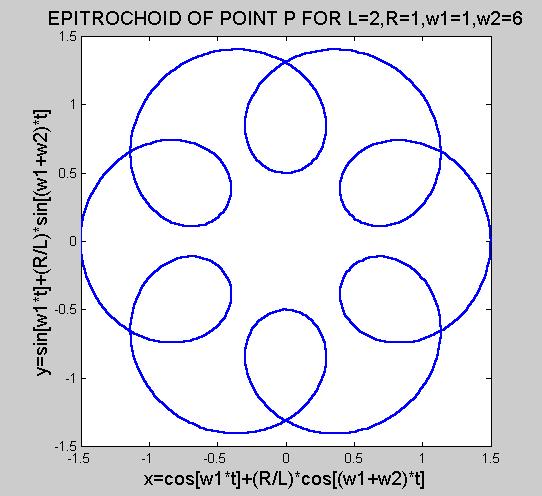
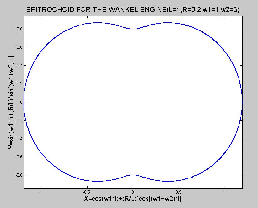
EPITROCHOID PATH OF A POINT
P: In our class discussion we
derived the velocity and acceleration of a point P on a rigid
rotating body when measured relative to an inertial frame of
reference. We use this procedure here to determine the rather
complicated path a point P located at the periphery of a
rotating disc of radius R and angular velocity w2 when the
disc axis located at moving point A is attached to a bar of
length L at one end while the other is fixed at O. The
position vector of P relative to O is then rP/O=rA/O+rP/A=
{I*Lcos(w1*t)+Lsin(w1*t)}+ {i*Rcos(w2*t)+j*Rsin(w2*t)}, where
w1 is the angular velocity of the bar L. Now from the geometry
we have that i=I*cos(w1*t) +J*sin(w1*t) and
j=-I*sin(w1*t)+J*cos(w1*t). Substituting this relation between
the base vectors i,j and I,J , we find the X and Y components
of the position vector rP/O to be-
X=L*cos[w1*t]+R*cos[(w1+w2)*t]
and
Y=L*sin[w1*t]+R*sin[(w1+w2)*t].
This is the parametric
representaion of the famous epitrochoid. We show you HEREthe
result
when L=1, R=0.5, w1=1 and w2=6. The ability to visualize
such paths in two and three dimensions is a valuable skill
possesed by many design engineers such as Felix Wankel , the
inventor of the Wankel rotary engine. Go HERE
to see the epitrochoidal shape of a Wankel engine housing
generated by the above formulas when L=1, R=0.2, w1=1, and
w2=3.
Lecture 15- SECOND HOUR
EXAM . Will follow the same format as the first exam
with 3 out of 4 questions to answer. You are responsible for
all materials covered in class since the first exam, however,
the emphasis will be on Impulse and Momentum andthe
Kinematics of Rigid Bodies, and the material covered in the
homeworks and the lectures. The exam is closed book, except
you can bring one 3"x5" card.
Lecture 16-Introduction
to
Kinetics of Rigid Bodies. Basic Laws of Plane Motion. Spin-up
of a FlyWheel . Disc rolling down an incline. Review of Mass
Moments of Inertia and the Identity for Plane Motion that H=I*w or dH/dt=I*a. Moments
of Inertia for the Disc, Rod, Plate and Sphere. Parallel Axis
Theorem.
BASIC LAWS OF MOTION FOR A
RIGID BODY: We have now reached
the point in our dynamics course at which you are capable of
calculating the behaviour of a translating and rotating rigid
body subjected to a collection of forces and moments. You need
only use the two basic equations of kinetics, namely, F=mA and M=dH/dt, where A
is the acceleration of the center of mass of the body , F is
the sum of the externally acting forces, M represents the sum
of the moments acting about the center of mass( or a zero
velocity point) of the body, and H is the angular momentum
about the same point. In 2D these two vector expressions
reduce to a total of four algebraic equations, which when used
in conjunction with our kinematic relations for a rigid body,
make most dynamics problems soluble. Note that one recovers
the basic laws of statics when A and H are zero.
Lecture 17-More
problems worked for Rigid Body Plane Motion. The falling rod
hinged at one end. Acceleration of an automobile. Center of
Percussion. The Compound Pendulum. Falling Rod on Smooth
Surface.
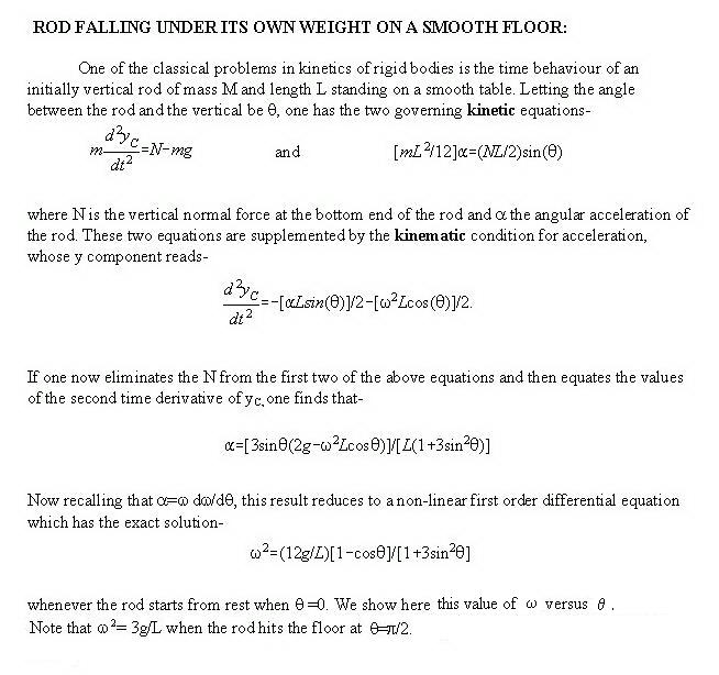
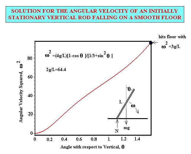
THE FALLING ROD PROBLEM:
In class today we discussed one
of the more interesting problems encoutered in dynamics,
namely, the behaviour of a uniform rod initially standing
vertically on a smooth floor. I summarize the governing
kinetic and kinematic conditions governing the rod HERE. Note that
the rod's angle relative to the vertical as a function of
time is determined by a solution of a highly non-linear
second order differential equation for theta as a function
of time which can only be solved numerically. Alternatively,
you can plot the square of the angular velocity versus angle
directly as done HERE. This last result is also possible to obtain
directly by use of energy methods. A numerical
integration(using Runge-Kutta) for q versus
time
shows that it takes about 0.88 sec for the rod to hit the
floor when L=1meter and the rod is started from rest
at
q(0)=0.01 rad. This
time increases with increasing rod length L and decreasing
acceleration of gravity g.
Lecture 18-Work
Energy
Principle for Rigid Bodies. Kinetic Energy for a Rotating Body.
Solving the "cylinder rolling down an incline" problem by the
work-energy method. Rolling cylinder produced by spring force.
Some Conservation of Energy Problems. Introductionto
Impulse-Momentum Principle for Rigid Bodies.
Lecture 19-(Last Lecture on New
Material)- More on the Impulse-Momentum
Principle. Conservation of Angular Momentum. Angular Impact.
Center of Percussion. Oscillation Frequency of a Rigid Body.
Brief discussion of Vibrations.
A BILLIARD BALL PROBLEM: A problem often posed in dynamics is -At what
height h above a table should one hit a stationary billiard
ball of radius R in order to have it roll without slipping?
This is a problem involving angular impulse plus the kinematic
condition that when rolling we have V(the speed of the mass
center)=omega*R. Applying the angular impulse formula about
the contact point C between the ball and the table, we have
that h*Fdt=IC*omega, with IC=2/5 m
r^2+mr^2=7/5 m r^2 by the parallel axis theorem. Also,
applying the linear impulse principle to the ball's mass
center, we have Fdt=mV, if we assume the contact friction is
neglibgible. So eliminating the impulse term Fdt, one finds
that omega*R*h=(7/5)R^2*omega. On cancelling the R and omega
terms, this says that the billiard ball will roll without
slipping if it is hit by the cue stick at height h=(7/5)R
above the table surface. Try it the next time you are playing
billiards.
Lecture 20-Review for Third Hour Exam. Emphasis will be on Planar Kinetics,
Work-Energy for Rigid Bodies, Impulse-Momentum for Rigid
Bodies, and Vibrations. Same format as first two exams with 3
out of 4 questions to answer from material covered in the book
and lectures. Closed book, but one 3"x5" card allowed. Filling out of teacher evaluation forms.
OSCILLATION FREQUENCY OF
A MASS VIA THE RAYLEIGH PRINCIPLE: Consider a mass m free to rotate about a pin
at A located at distance d from its mass center C. Under
resting conditions point C will lie on the same vertical
line as A. Next put a small clockwise displacement on C
corresponding to a very small displacement angle theta about
point A of line A-C. Letting go of the mass at this new
angle, where the potential energy is V=mgd[1-cos(theta)] or
approximately V=(1/2)*mgd*theta^2, will result in the
oscillation of the mass. The maximum kinetic energy will be
present at the bottom of the subsequent swings and equals
T=1/2*(mk^2+md^2)*[d(theta)/dt]^2. Representing the
resultant oscillatory motion by theta=(max
theta)*sin[omega*t] and realizing from the conservation of
energy and Rayleigh's Principle that Vmax=Tmax, we find that
(omega)^2=gd/(k^2+d^2), where k is the radius of gyration
about C. Thus a yard stick will oscillate about its end with
an omega of sqrt[3g/2L]=4.01r/s or a period of
tau=2*pi/omega=1.56 seconds.
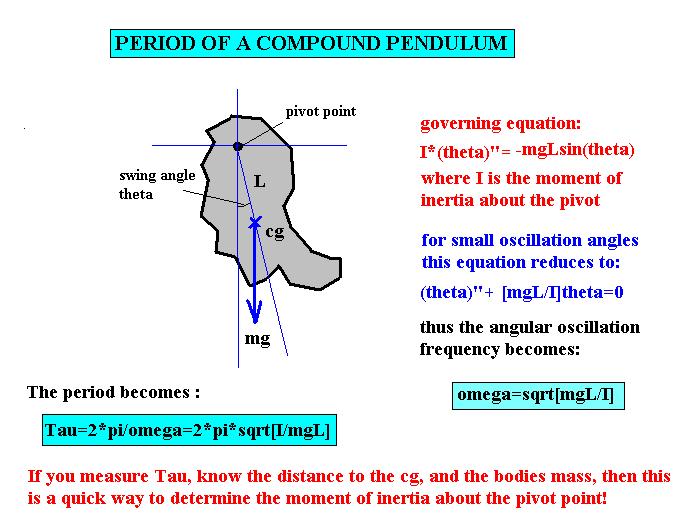
PERIOD OF A COMPOUND
PENDULUM: A classic problem in
the area of oscillations is that of the period of a compound
pendulum. The question which is asked is what is the period
of oscillation when one pivots an arbitrary shaped mass
about a point other than its center of gravity and releases
the mass with its cg slighly away from the vertical line
passing through the pivot point. Clearly this sets the mass
into oscillation and for small maximum swing angle leads to
the result that w=sqrt(mgL/I) as
shown by clicking HERE.
For several years now I have had students from Mechanical
Engineering come by and ask me how one might determine the
moment of inertia of a connecting rod experimentally. The
usual answer one gives is to use an Atwood machine. But a
really much simpler way is to treat the connecting rod as a
compound pendulum and measure its oscillation period
experimentally.
Lecture 21-THIRD HOUR EXAM. Can pick up graded exams in front of my office
in three days. There will be no
final exam for the course. To remind you, course grades are determined
as follows:
G=[(Sum
of Three Class Exams)/90]x90+[(Sum of Homeworks)/21]x10
This means 90% for the three tests and 10%
for the 21 homework problems you worked on during the
semester.
Other of our WEB pages are
found at:
https://web.mae.ufl.edu/uhk/MATHFUNC.htm
https://web.mae.ufl.edu/uhk/ANALYSIS.html
https://web.mae.ufl.edu/uhk/RESEARCH.html
https://web.mae.ufl.edu/uhk/HOMEPAGE.html
https://web.mae.ufl.edu/uhk/STATICS.html
https://web.mae.ufl.edu/uhk/STRENGTH.html
